100 MΩ if 0.50 to 0.80mm
pitch
500 MΩ 1.00mm pitch upwards
Breakdown voltage
at 60 Hz:
500V min.
Capacitance:
< 1 pF
Inductance:
< 2 nH
Operating
temperature:
-55°C to +125°C ; 260°C for
60 sec.
These
sockets are available for almost any IC
package style, size, lead-count and
lead-pitch down to 0.5mm pitch: BGA, MLF/QFN,
uBGA, SOIC, QFP and also custom packages or
die. Furthermore, these sockets provide
flexibility in the PCB mounting method: SMT,
raised SMT, through-hole, or compression
mount.
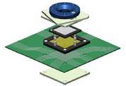
SMT (pin
type -30) uses a standard reflow process
to mount the sockets to the target PCB.
These sockets mount in the same
footprint as the IC, but typically
require a mimimum clearance of 6mm
betyond the package's periphery. In
situations where adjacent components lie
in this area, either the socket body can
be modified to clear the components, or
a special raised SMT (pin types
-28 or -29) pin can be used in place of
the standard SMT pin. These pins raise
the socket body from 2-5mm above the
PCB. Although this method does not
require any drilled holes in the target
PCB, it is highly recommended to provide
two such plated holes in order to
accomodate mounting pegs and greatly
strengthen the physical connection
between the socket and PCB.
Alternatively, epoxy can be used to
strengthen the connection, but this more
or less creates a permanent bond between
the socket and PCB.
Through-hole
(pin type -70) requires plated holes to
be drilled in the PCB into which the
pins of the socket will be soldered.
This provides for a very robust and
reliable electrical and mechancial
connection. However, the electrical
performance is reduced due to the longer
pin lengths. This method is highly
suitable for burn-in applications.
Compression
(pin type -90) mount removes the need
for any soldering and just requires the
socket to be held to the PCB via screws.
The benefit of this method is that it
allows the customer to easily attach the
socket to the target board in the lab,
without the extra cost, lead-time, and
potential problems caused by sending the
board to an assembly house. However,
this method requires that the target PCB
has mounting holes drilled to accomodate
the mounting screws and socket body
alignment posts. Furthermore, depending
on the size of the IC, the PCB
thickness, etc., a backing plate is
required to provide rigidity and ensure
the socket pins contact the PCB pads.
This plate can usually be modified to
accomodate any backside compononents.
SMT (-28,
-29, -30)
Through-Hole (-70)
Compression (-90)
SOCKET BODY VERTICAL OFFSET
The following table shows
the vertical clearance of the socket body
from the PCB. This is only applicable to the
SMT mounting style. In situations where the
clearance is insufficient, or the standard
SMT pin is preferred, it is possible to
modify the socket body to accomodate for
adjacent components.
Pitch
Vertical Offset Using Special Raised
SMT
(-28)
Vertical Offset Using Raised SMT
(-29)
Vertical Offset Using Standard SMT
(-30)
0.50-0.75
N/A
2.3
0.4
0.8
4.5
2.8
0.6
1.00
4.5
3.2
0.8
1.27
N/A
5.0
1.2
Dimensions in mm
FEATURES & BENEFITS
Easily exchange
ICs in your system
High bandwidth:
3GHz @ -1dB
Available for any
IC package style: BGA, uBGA, CSP, QFN/MLF,
LGA, PGA, SOIC, QFP, custom or die
Any lead count,
grid and package size
Minimum 0.5mm
lead pitch
Maximum 40g force
per contact
Mounts to same
PCB footprint as the IC (no holes
required for SMT version)